hi all
I am completely new to this topic, but I stumbled upon the PiMOST and it immediately piquet my interest.
It all started with the FM shutdown in my country at the turn of the year. My car has a great sound system, but now all that’s left is a 6-disc CD changer, an AUX port and a a very outdated navigation system. As in the past I could use my phone for navigation and stream music over the AUX port or update my car (if not already present) with a bluetooth module. Apparently, there is no replacement head unit available for my specific car (SAAB 9-3, 2006), so I thought about alternative solutions:
-
I could buy one of this portable CarPlay/Android Auto units, but I don’t like the idea of mounting an additional screen on the dashboard. If it’s not the phone solution that I currently use, it would require a much more integrated solution.
-
I thought about buying and disassembling a cheap small portable unit (e.g. for motorbikes) and replace my existing 5.8“ screen (connected to the AUX port). However, some of the settings (like balance e.g.) would need to be set blind on the head unit and more importantly - it may look integrated, but all the steering wheel controls would be lost. If I invest something in an integrated solution, then only with with workin steering wheel controls.
-
I found an amazing project from Saab Unleashed with a Pi and a touchscreen creating the same independent solution as with the portable unit or dankfred’s super cool I-Bus integration with a Pi, an additional microcontroller and a CAN module. Both running on (the discontinued) Open Auto Pro. It might be possible to replicate dankfred’s project with available versions of Open Auto (Pro).
Looking for alternative head unit emulators I finally found Rhys React-Carplay and his unique PiMOST.
@rhys_m It looks like you invested A LOT in in your projects, creating everything from scratch - highest respect for you and your work!
@keshka Did you manage to get things working on your SAAB 9-3? I know it has been more than a year since your last post, but I would be very interested in any information that you would like to share, especially if we do have the same car generation (2003-2006). From the picture of your CD player I can see that at least the CD player has been manufactured in 2003, so it looks promising ![]() Have you managed to verify the MOST-bus frequency of 44.1kHz?
Have you managed to verify the MOST-bus frequency of 44.1kHz?
I do have a SAAB 9-3 NG (II/SS) pre facelift (YS3F) 5-door from 2006 with prestige 300 sound system.
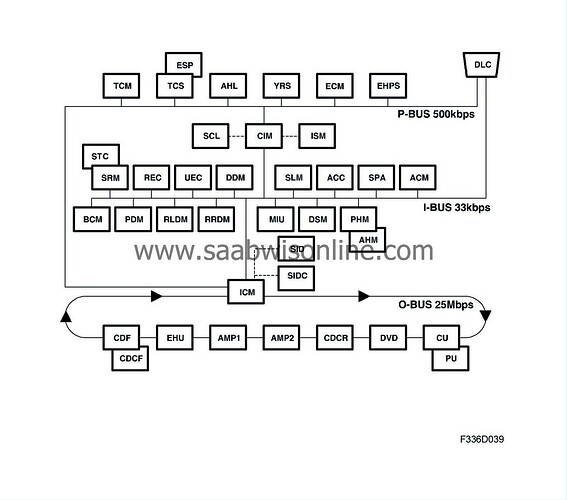
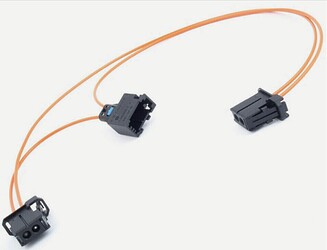
There are three types of bus communication: P-bus (Powertrain Bus), I-bus (Instrument Bus) and O-bus (Optical bus). The audio system communicates via the O-bus together with the navigation system, the telephone system and others. The O-bus is optical and is a ring bus. Two fibre optical cables are connected to each control module on the bus, one fibre optical cable for receiving and one for sending. Messages received are converted by each control module from a fibre optic signal to electrical and then converted back to optical for sending. The O-bus data transfer rate is 25 Mbit/s.
source
Therefore, the O-bus is a MOST25 bus which would be compatible to the PiMOST, frequency most likely 44.1kHz(?). My biggest question at the moment is what would be the best/easiest way to integrate it into the existing equipment and what would be the benefits for each solution.
At the moment I see the following potential solutions:
A) replacing the ICM head unit completely, hence the PiMost would be the new MOST master. I believe this would allow to do almost anything that could be done, including a retrofit of a touch screen in the dashboard. But it also sounds like a lot of work, since all Interfaces to the ICM (P-Bus, I-Bus and other interfaces such as SID, SIDC,…). Although there is some information available for the SIDC and the I-Bus (and with access to the forum here) it seems like a lot of work that needs to be done - sniffing all the required messages for all 3 bus systems (an additional interfaces) and handling over the correct information to the correct device. Of course it would also require an additional CAN bus channel on top of the existing one in the PiMOST (like the MCP2515).
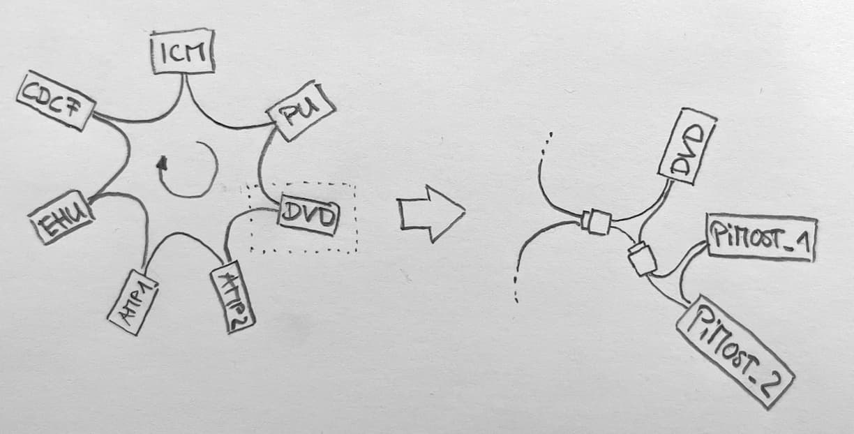
B) replacing one of the existing components such as the DVD unit (maps for the navigation system) and/or positioning unit which most likely has „the rights“ (if something like this exists?) to get notified about lot of data (maybe even microphone input?), sending audio (and video?) over the MOST. In this case it might be possible to use the existing screen in the ICM (i know it has a poor resolution, and I might run into the „change resolution carlink“ topic). In CarPlay it might be possible to cycle through the menu with the existing knobs/wheels or maybe just with Siri. I’m a bit scared of the „security on MOST“ which checks for approved serial numbers. It looks like not only some Volvo’s are protected with what they call theft-proof. It might be possible to see the required data with the divorce/marriage function of a Tech2? Adding the PiMost to the existing ring and sniffing the answer from the existing DVD unit before the PiMOST will be set to disable mode might works as well - does anyone have experience with this? Additional Information about this topic at the end of this post.
C) Adding the PiMOST to the MOST without removing anything would require to update the list of control modules in the ICM. It looks like this would be possible with a Tech2, but maybe only for predefined OEM components (such as the CD changer rear)? Anyone knows more about that or how to achieve it without a Tech2? In this case it might be possible to get notified about all available data and also have „the rights“ to stream audio/video over the MOST
Does this make any sense? Or would there be easier ways to achieve the integration of the PiMOST?
I guess any input from anyone would help me a lot, since you most likely had to take care about the same topics for your project.
If I misunderstood something, please also give me a hint - I am willing to learn ![]()
For anyone who would like to read more information about the MOST in my car and maybe give a specific advice/answer here’s a collection source:
- I-bus, one lead:
When the key is inserted into the ignition, the CIM (Column Integration Module) wakes the other control modules on the I-bus by briefly sending B+ over the bus. The CIM then sends regular reports over the bus of the key position.
- P-bus, two leads:
The P-bus system has a +15 lead coming directly from the ISM (Ignition Switch Module). With the ignition switched on, communication goes on continuously. Communication stops as soon as the ignition is switched off. The P-bus does not have a wake-up function similar to that of the I-bus.
- O-bus, MOST25 ring bus:
None of the modules on the O-bus have a +15 lead. All the modules wake up when they receive a light pulse and remain awake so long as a module is communicating. Pressing a button on the ICM (Infotainment Control Module) is the most reliable way to wake the bus immediately.
The ICM is the master in the MOST bus and also acts as a gateway to the two CAN bus systems I-Bus and P-Bus. The ICM (with its own display) is also the control unit for the Saab Information Display „SID“ and the SID control Panel „SIDC“ (5V 960Hz PWM signal). Both connected through what they call a C-cable (serial bidirectional 10kbit/s single wire bus for slow communication between two modules).
source
MOST-Bus Components (italic assumingely not present in my car):
- Control panel, infotainment, ICM (736)
- Communication unit, Positioning unit, CU/PU (468/635)
- Unit, DVD (729)
- CD Changer Rear, CDCR (355R)
- Audio System Amplifier, rear speakers, AMP2 (354R)
- Audio System Amplifier, front speakers, AMP1 (354F)
- Entertainment head unit, EHU (353)
- CD player/changer, front, *CDF/*CDCF (355F)
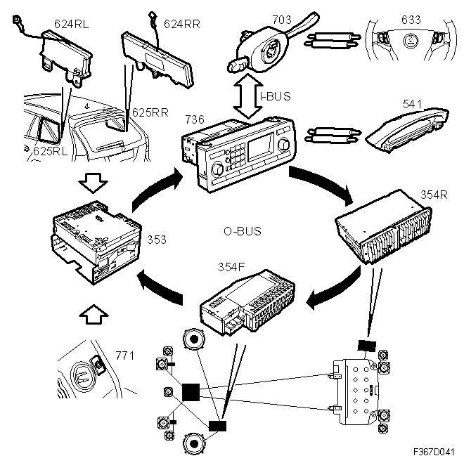
The prestige 300 sound system involves two additional physical amplifiers (connected through the O-Bus) on top of the amplifier in the Entertainment Head Unit (EHU).
@rhys_m Is it possible to add more than one amplifier in the react-Carplay configuration?
source
- Entertainment head unit, EHU (353)
- Audio System Amplifier, front speakers, AMP1 (354F)
- Audio System Amplifier, rear speakers, AMP2 (354R)
- Control panel, infotainment, ICM (736)
- SID (541)
- Speakers, dashboard, left/right (266 FL/FR)
- Speakers, rear, left/right (266 RL/RR)
- Speaker, dashboard, centre (266 FC)
- Speakers, front door, left/right (266 LH/RH)
- Speakers, woofer, rear (266 RCW)
- Antenna (625 RL/RR)
- Antenna amplifier, radio (624 RL/RR)
- Steering wheel controls (633)
- Column Integration Module, CIM (703)
- Connection, AUX (771)
The audio system communicates via the O-bus together with the navigation system, the telephone system and others.
source
source
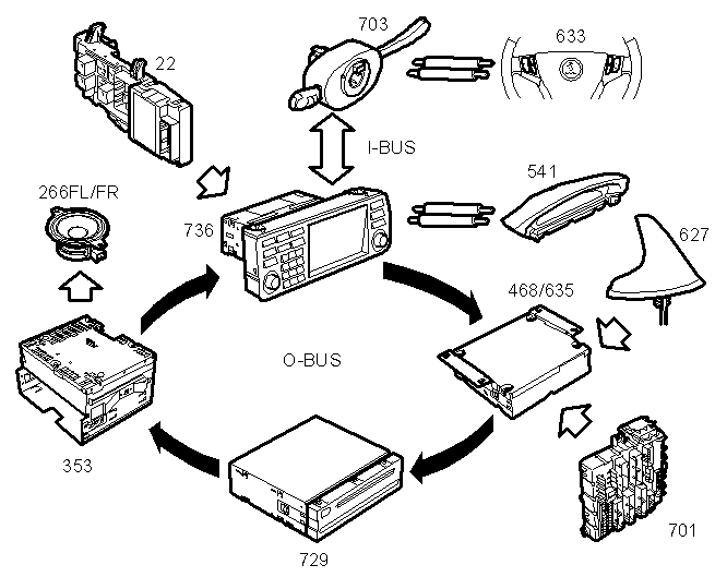
- Electrical centre, dashboard (22)
- Speaker (266 FR, FL)
- Entertainment Head Unit, EHU (353)
- Antenna, GPS/GSM (467)
- Navigation unit, CU/PU (468/635)
- SID (541c)
- Steering wheel controls (633)
- Rear Electrical Centre, REC (701)
- DVD unit (729)
- Control panel, Infotainment system 3, ICM3 (736c)
Additional information about components MOST, „marriage“ to the car, respectively security on MOST in my car:
Additional control modules can be connected. Each control module must be connected to a specific place in the ring as compensation has been made for the short delays in communication.
source
It is very important that everything connected to the O-bus is connected in a specific order, see illustration, and that the ring is closed the whole time. Connection in any other way than that described in these fitting instructions may result in several of the car’s systems failing to work.
source
ICM contains a list of the control modules on the O-bus and can compare this list with incoming bus messages to determine the location of a break on the O-bus. The diagnostic tool is used to update the list of control modules in ICM when a new control module is fitted to the O-bus. The P-bus and I-bus are wired to the data link connector. Tech 2 can be connected with an adapter to the data link connector and communicates directly with the various control modules on the P-bus and I-bus. Diagnostics communication with O-bus systems takes place via the ICM, which acts as a gateway.
source
… , all O-bus control modules provide diagnosis and generate a DTC if they receive a corrupt message. All messages received are converted into electrical signals, reconverted into light and retransmitted. The ICM is the bus master and, unlike the other modules, never resends a corrupt message. If a control module receives a corrupt message, the fault must have occurred upstream, somewhere between the control module and the ICM. This means that a fault will generate a DTC for an intermittent bus fault in all the control modules downstream.
source
The ICM contains lists of all the control modules on the three busses in the car in question. When you read out DTCs, Tech2 always starts by contacting the ICM to check which control modules should be present in the vehicle. Tech2 then checks which control modules in the car are communicating. If a control module is missing, or if an additional control module has been fitted, this is displayed. Nothing is displayed if the numbers of identities agree. If there is a difference, you are given the opportunity to start fault diagnosis or to accept the new control module configuration. You may wish to accept the new configuration if a control module has been fitted or permanently removed. Tech2 will then update the lists in the ICM so that no warning is displayed in the future. Tech2 displays if a control module on the bus is missing. This means that if all control modules connected to the buses are communicating correctly, the diagnostic tool does not display a warning. If one of the O-bus systems is missing, the entire O-bus will be down, and in which case there will be a DTC in the ICM. To find out where the break is, disconnect then reconnect the battery cable. All O-bus systems will then be initiated at the same time, allowing the ICM to calculate how many control modules sent a light signal, in other words, how far back along the ring the break is.
source
